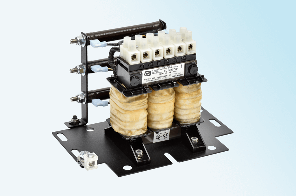
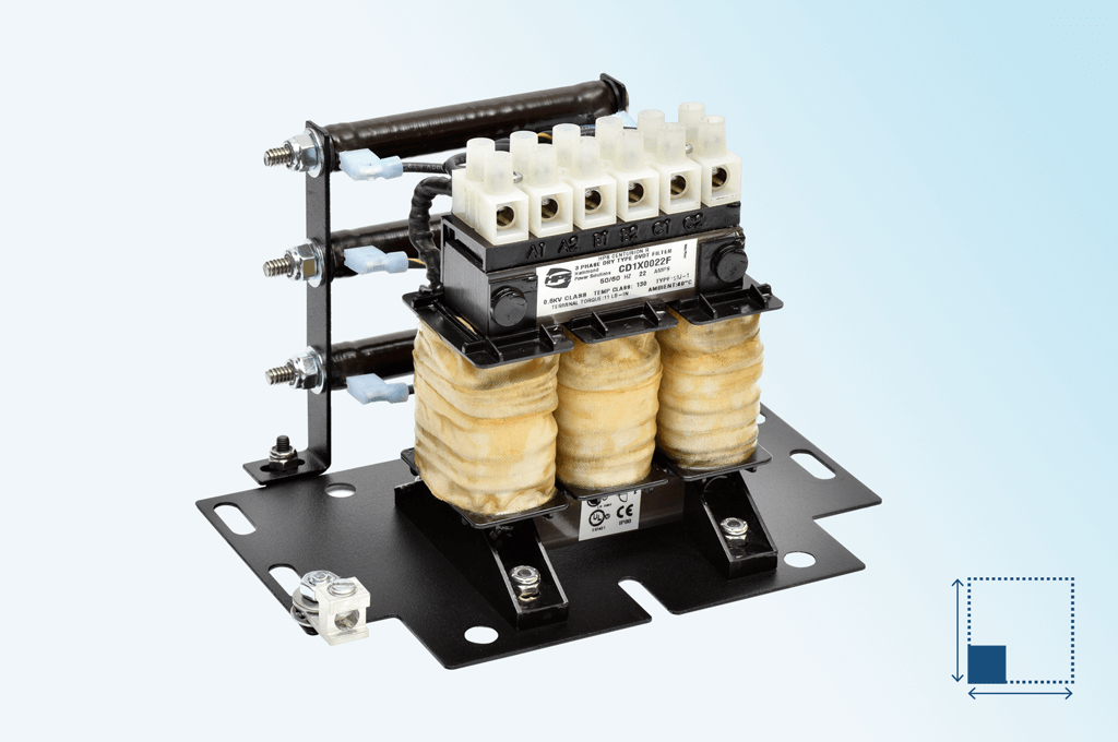
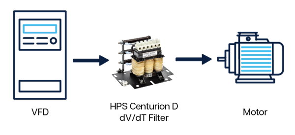
The HPS dV/dT filters are specifically designed for use between variable frequency drives (VFD’s) and motors when longer cable lengths are used.
The dV/dT filter combines an inductor and parallel resistor network to mitigate both high frequency components and voltage spikes between the VFD and motor. The filter can mitigate the effects of reflected wave voltages greater than what a reactor alone can accomplish. The filter provides protection to the motor by slowing down the rate of voltage increase and minimizes the damaging peak voltages that occur within the motor’s windings and along the length of cables feeding the motor.
Witness real time testing of our dV/dT filters in the HPS Power Quality lab. Learn more here.
Operation Principle
The term “dV/dT” refers to the change in voltage over change in time. With regards to VFD’s, dV/dT is explained as the rapid change in voltage at the beginning or end of the square wave pulses that make up the pulse width modulated (PWM) output of a VFD that powers the motor. As the square wave pulses travel the electrical cable to the motor, the differences in impedance between the cable and motor windings cause some energy in the pulse to be “reflected”. In applications where the distance between the motor and VFD is long, the voltage of two pulses can combine in the cable or motor windings. This creates a high voltage condition of twice or more the VFD’s DC bus voltage. Applications with long cables between the VFD and the motor can experience peak voltages up to 1600V in a 480V system and up to 2100V in a 600V system. These high peak voltages will cause motor winding failures and premature motor insulation failure resulting in down time and lost revenue.
- System Voltage Rating up to 600V (480V-600V applications)
- Current Rating of 2A to 750A
- Inverter Switching Frequency 2kHz to 4kHz
- Inverter Operating Frequency up to 60Hz
- Insulation System of 130°C (2A - 54A), 180°C (>55A)
- Voltage Drop of less than 3%
- Up to 1000ft (600ft & 1000ft models available)1,2
- Peak Voltage at Motor of 150% of DC bus voltage
- cUL Listed
Environmental Product Characteristics
- Ambient Operating Temperature:
- Open Style: up to 50°C
- Enclosed Style: up to 40°C
- Altitude: <1000m
- Cooling Method: Natural Convection
- Enclosure Type: Open, Type 1, Type 3R
Notes:
1VFD rated cable recommended
2Maximum motor cable size to achieve 5% voltage drop (including 2% from the filter)
Maximum lead length and carrier frequency can vary depending on motor cable type
Product Catalogs and Literature
Instruction Sheets and Manuals
Technical Specifications
Other Resources

Technical Support
Leverage many tools to assist you with your technical questions: Customer Service, FAQs, Troubleshooting Guide, Installation Manuals, Instruction Sheets and Webinars.

FAQs
Get answers to our most frequently asked questions.