
From Grid to GPU: A Practical 800Vdc Power Architecture for AI Factories
How AEG Power Solutions enables a proven, scalable path to facility-level DC power
Executive Summary
The rapid growth of artificial intelligence is reshaping the electrical design of the data center. NVIDIA’s 800Vdc roadmap identifies the legacy 48-54Vdc rack-distribution architecture as a bottleneck for next-generation AI factories, while the Open Compute Project (OCP) is advancing common low-voltage DC architectures and interfaces for increasingly dense racks. AI racks are moving from tens of kilowatts toward hundreds of kilowatts and megawatt-class systems. At these densities, conventional 415/480Vac distribution and low-voltage rack power create a growing penalty in current, copper, conversion equipment, heat, and usable floor space.
Facility-level 800Vdc distribution architecture offers a practical response aligned with the direction described by NVIDIA and current OCP work. Instead of carrying low-voltage AC deep into the data hall and repeating AC-to-DC conversion at every rack, a central conversion system creates a regulated DC backbone that feeds high-density compute directly. This shorter path can reduce conversion losses, simplify distribution, reduce the use of copper, and connect energy storage directly to the bus.
A Transformer-Rectifier Unit provides a practical, deployment-ready solution for meeting the rapidly increasing power demand of AI factories. By combining medium-voltage transformation, galvanic isolation, and controlled solid-state rectification in one coordinated power block, the architecture creates the regulated 800Vdc backbone required for high-density computing. AEG Power Solutions’ DC3 and DC4 platforms perform the critical rectification and power conversion functions that enable this approach. Under stated assumptions, this architecture can deliver medium-voltage-to-800Vdc with approximately 98.5% efficiency, utilizing 1.6 MW modules – up to 12.8 MW in an eight-module system.
The conclusion is straightforward: operators can establish the facility-level 800Vdc backbone now using a Transformer Rectifier Unit. This solution relies primarily on existing conversion technology, such as the AEG DC3 and DC4 platforms, while supporting OCP-compatible 800Vdc and ±400Vdc configurations and preserving a path toward 1500Vdc. Solid-state transformers (SST) are entering commercial introduction, and industry specifications are developing through OCP. However, compared with established transformer-rectifier architectures, full-scale SST systems have limited multi-year fleet history in AI data center service, while certification, protection coordination, internal fault management, service practices, and lifecycle performance continue to be validated. A Transformer-Rectifier Unit therefore provides a lower-risk path to deploying the 800Vdc backbone without making project schedules dependent on the broader maturation of the SST ecosystem.
The Architectural Imperative
AI factories are not simply larger conventional data centers. NVIDIA describes increasingly dense GPU systems as requiring a new power architecture with fewer stages from the grid to the chip. The power system must support both unprecedented density and a highly dynamic, synchronized load profile [1]-[6].
At the rack, current is the immediate constraint. Supplying one megawatt at approximately 54Vdc requires more than 18,500A. Supplying the same power at 800Vdc requires approximately 1,250A. NVIDIA’s published architecture positions 800Vdc as the practical route to one-megawatt racks, while OCP work is defining the supporting rack, protection, and distribution ecosystem.
As Figure 1 shows, frontier AI rack power is expected to increase sharply through 2030, reinforcing the need for a higher voltage power-distribution architecture.
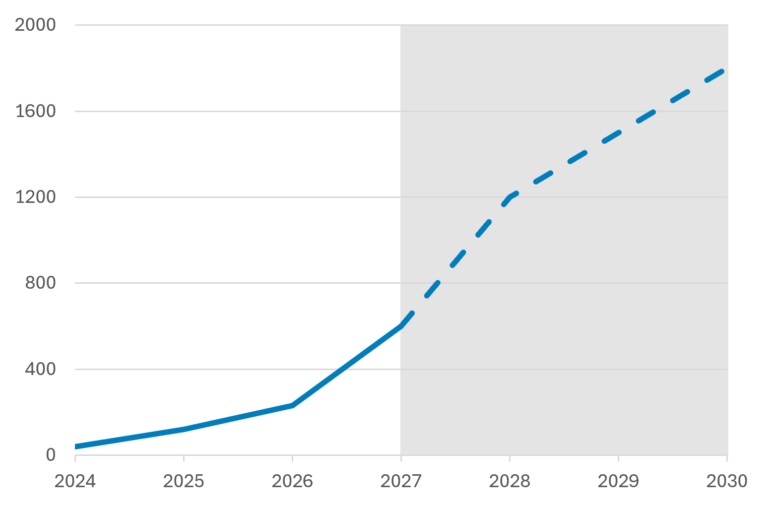
Figure 1. Estimated frontier AI rack power in kilowatts by release year, 2024–2030. [9]
Conventional Power Chain Reaches Its Limit
The traditional data center power train was designed for a different era of computing. Medium-voltage AC is stepped down to 415/480Vac, conditioned through a UPS, distributed through low-voltage switchboards and busway, and converted to DC inside every rack. NVIDIA’s 800Vdc architecture focuses on reducing these repeated conversions so that more available power reaches the compute load.
The source technical analysis estimates that legacy architectures typically deliver less than 90% to 94% end-to-end efficiency, depending on equipment and operating conditions. A facility-level 800Vdc architecture can achieve approximately 97% grid-to-rack efficiency under the stated assumptions. OCP’s LVDC work similarly treats native DC distribution, energy storage, protection, and rack interfaces as parts of one coordinated system.
A More Direct Path From the Grid to Compute
Facility-level 800Vdc moves the primary AC-to-DC conversion out of the rack and into a central power block. This mirrors NVIDIA’s target architecture: a single AC-to-800Vdc conversion followed by direct DC distribution to the compute rack. The approach removes the low-voltage AC layer from the new power path and reduces the number of times full power must be processed. The DC backbone also provides a natural point of connection for smoothing and backup.
Figure 2 compares the two power paths. The facility-level architecture removes the low-voltage AC distribution layer, the double-conversion UPS, and repeated rack-level AC-to-DC conversion from the main path.
Legacy Low-Voltage AC Power Train
Transformer
Distribution
Facility-Level 800 VDC Architecture
Rectifier Unit
+ Storage
Distribution
Figure 2. Single-line comparison of the legacy low-voltage AC power train and the facility-level 800Vdc architecture. Adapted from the source technical analysis and NVIDIA references [1]-[3].
NVIDIA’s work emphasizes integrated, multi-timescale storage, while OCP’s LVDC architecture considers bus-level storage and protection as core system elements
Central Rectification, Not a Permanent Sidecar
Sidecar power systems offer a useful transition option for existing buildings, including the OCP Mt. Diablo / Diablo 400 approach. However, a sidecar setup retains the upstream 415/480Vac distribution system. Central rectification addresses the complete power path by converting medium-voltage AC to 800Vdc at facility level. This is the target architecture for greenfield AI factories and major expansions.
The AEG Approach to Facility-Level 800Vdc
AEG Power Solutions combines a high-efficiency line-frequency transformer with an industrial high-efficiency solidstate rectifier. The transformer provides voltage conversion, transient protection, and galvanic isolation. The rectifier provides controlled DC output, grid-quality current shaping, dynamic response, and coordinated protection. The resulting Transformer-Rectifier Unit could, in certain conditions, supply the common 800Vdc backbone promoted across NVIDIA’s architecture and the broader OCP ecosystem.
DC3 rectifier uses a hybrid multipulse rectifier followed by an active chopper. DC4 uses a three-level active front end that combines rectification, current shaping, and output control in a single conversion stage. At 800Vdc, DC4 supports 1.6 MW per module and up to 12.8 MW in an eight-module containerized system. The platform can serve unipolar 800Vdc or split ±400Vdc configurations, supporting both NVIDIA and OCP architecture options [7].
Efficiency and Grid Performance
A modern medium-voltage transformer operating at approximately 99.5% efficiency in series with a rectifier operating at approximately 99.0% produces about 98.5% combined efficiency. DC4 is designed for power factor above 0.99, total harmonic current distortion below approximately 2 to 3% at nominal load, and zero-to-full-load response in less than 10 milliseconds under the stated conditions.
Protection is a central design challenge in 800Vdc architecture. Unlike AC systems, DC fault current has no natural current zero crossing, while distributed bus capacitance and connected energy storage can release substantial energy into a fault. Protection must therefore detect and isolate faults rapidly, control capacitor discharge, coordinate converter current limiting with interruption devices, and maintain selectivity between protection zones. AEG addresses these requirements through a layered architecture that combines high-bandwidth current sensing, converter-level current limiting and solid-state circuit breaker. The line-frequency transformer provides galvanic isolation from the medium-voltage grid and protection of the rectifier.
Performance in Market Context
Figure 3 places published medium-voltage-to-DC systems on an efficiency-versus-power-density plane. The source analysis shows current full-scale SST demonstrators clustering around 98 to 98.5% efficiency, while a Transformer Rectifier Unit using AEG’s DC4 is positioned at approximately 98.5% with competitive system power density. The chart supports the near-term case for deploying a proven Transformer-Rectifier Unit without waiting for the next generation of SST technology.
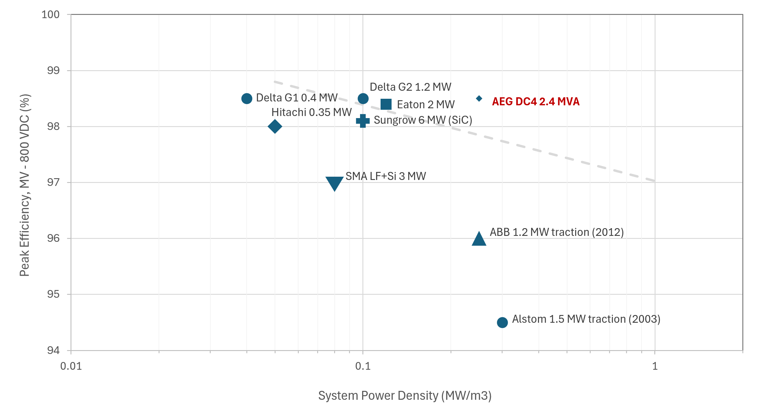
Figure 3. Peak efficiency versus system power density for published MV-to-DC SST demonstrators and products, with AEG DC4 and the ETH Zurich next-generation SST target for reference [7].
A Practical Alternative to Waiting for the Solid-State Transformer
Solid-state transformers remain an important emerging option, with potential advantages in density, modularity, bidirectional operation, and medium-voltage control. Figure 3 also makes the gap visible: the next-generation target sits beyond the performance of current full-scale demonstrators. NVIDIA is supporting an ecosystem that includes both transformer-based and SST pathways, while OCP work is developing common specifications and interfaces that can preserve downstream choice.
AEG’s architecture avoids making the 800Vdc transition dependent on the SST validation cycle. Both approaches terminate on the same facility DC bus. Operators can therefore build the busway, rack interface, storage system, and protection ecosystem now, then qualify alternative medium-voltage front ends as production evidence develops.
Business Value for AI Infrastructure Developers
Facility-level 800Vdc provides four practical advantages for AI infrastructure developers:
- More usable power. A shorter conversion chain allows a larger share of scarce grid capacity to reach the compute load, consistent with NVIDIA’s emphasis on minimizing end-to-end conversion stages.
- Better use of space and materials. Higher DC voltage lowers current, reduces pressure on copper and busway, and removes rack-level AC power shelves from the target architecture.
- Faster, lower-risk deployment. Existing industrial rectifier platforms and standard transformer interfaces provide a defined route to the 800Vdc backbone envisioned by NVIDIA and OCP.
- A protected technology path. A common 800Vdc backbone supports current rack roadmaps, OCP-aligned interface development, direct storage integration, and a later transition toward 1500Vdc.
Deployment Strategy
For greenfield AI factories, deploy the AEG DC3/DC4 platform as the production foundation for centralized 800Vdc power blocks, with the DC bus, rack interface, storage connection, and protection system engineered as one coordinated architecture. Compared with SST solutions that are still building full-scale operating and service evidence, DC3/DC4 provides a proven, scalable, and serviceable path to deployment without delaying the 800Vdc transition. Use sidecars where existing AC infrastructure must be retained and evaluate SST pilots separately as the technology and supporting OCP specifications mature.
Conclusion
NVIDIA’s roadmap and OCP’s ecosystem work reinforce the direction of travel: AI factories need a higher-voltage DC backbone, fewer conversion stages, practical pathways for existing facilities, and common interfaces for rack power, storage, and protection. Facility-level 800Vdc provides that foundation.
AEG Power Solutions offers products that make the transition practical today. A Transformer-Rectifier Unit combines mature transformer technology with advanced AEG DC3/DC4 rectification, delivering approximately 98.5% medium voltage-to-800Vdc efficiency under the stated assumptions, scalable multi-megawatt power blocks, strong grid performance, and a future path toward 1500Vdc.
Figure 3 strengthens the positioning: AEG DC4 operates in the same efficiency range as current SST demonstrators while relying on a proven, serviceable architecture. The common DC backbone allows operators to deploy now, participate in the NVIDIA and OCP ecosystem, and preserve future technology choice.
About the Solution
AEG Power Solutions provides industrial power conversion systems for demanding, high-power applications. For AI infrastructure, the DC3 and DC4 platform family can form the core of a facility-level medium-voltage-to-800Vdc architecture, integrating conversion, control, protection, cooling, communications, and bus-coupled storage.
PDF: Practical 800Vdc Power
Architecture for AI Factories
Source and Claims Note
This white paper was developed from “Powering the AI Factory: The Transition from AC to 800Vdc Architecture,” Revision 2, October 2026. NVIDIA and OCP references are used to establish industry direction and architecture context. Performance figures and comparative statements reflect the assumptions, engineering documentation, and cited references in the source technical paper. This document does not constitute a product specification or an offer. The products, solutions, and system configurations described in this paper are conceptual and forward-looking. In particular, the transformer rectifier unit discussed herein has not been commercialized or offered for sale by HPS or AEGPS. Accordingly, no representation or warranty is made so that any such product, solution, or performance outcome can or will be achieved. Readers should exercise caution and should not assume that HPS or AEGPS can, will, or intend to develop, commercialize, or deliver the products or solutions described in this paper. Any reliance on this paper is solely at the reader’s risk.