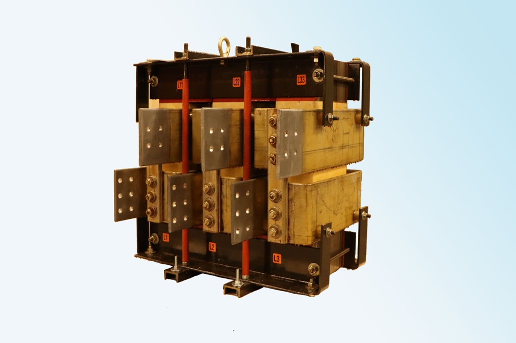
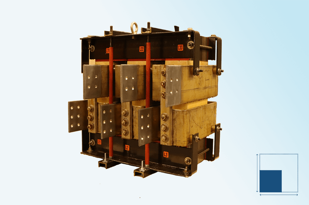
HPS offers Iron Core Reactors that are used in a wide variety of applications. The most typical applications are to supply inductance to mitigate current and voltage harmonics with non-linear loads. Reactors are used either alone or with capacitors and/or resistors in filter circuits.
Iron Core reactors, unlike Air Core reactors, have a core which saturates once design current levels are exceeded. Iron core reactors are typically not used in current limiting applications.
Types & Applications of Iron Core Reactors
- DC Link Choke
Filters and controls DC bus voltage and current in a variable frequency drives (VFD) and other rectifier circuits. DC Link Chokes smooth the ripple current flow to the VFD and help reduce AC input line current harmonic distortion while absorbing DC bus voltage.
- Filter Reactors
Used as a component of a filter to reduce harmonic levels in electrical power systems. Filter Reactors are used in a variety of configurations and are usually coupled with capacitors and/or resistors.
- Interphase Reactors
When paralleling two rectifier bridges an Interphase Reactor provides balanced system operation when both rectifiers are conducting by providing a high impedance between the two converters and low impedance to the load.
- De-Tuning Reactors
These iron core reactors are designed to limit the amount of harmonic current from non-linear loads on the reactor to the fixed impedance loads on components such as capacitors, transformers and cabling. De-Tuning reactors also mitigate voltage amplitude from increasing in circuits with non-linear loads.
- Power Factor Correction Reactors
Essentially these are de-tuning reactors specifically for use with power factor correction capacitors. They limit the amount of current present on the capacitors from harmonics to prevent heat and high current stresses to improve the capacitor’s operating life.
- Motor Starting Reactors
A series reactor designed to limit a motor’s inrush current during start-up by reducing the input voltage to the motor. Motor Starting Reactors have a short duty cycle and are switched out of the circuit once the motor has reached it’s rated speed. These are typically three phase reactors but less common schemes will use a reactor on only one phase or use an Air Core reactor.
- Line and Load Reactors
Line Reactors are used at the input of the VFD to mitigate harmonics and nuisance tripping as well as to reduce voltage line notches. Load reactors are used at the output of the VFD to mitigate the effect of long lead length (reflective wave phenomenon) and to reduce premature motor insulation failure.
- DC Smoothing Reactors
DC Smoothing Reactors are connected to DC system in series to reduce current ripples. DC Smoothing Reactors reduce harmonics on the DC waveform which in return reduces the losses and improve system stability and performance.
Product Specifications
- Voltage up to 46 kV
- Up to 250 kV BIL
- Up to 13000 kVAR
- Max AC Current = 4000 Amps
- Max DC Current = 6200 Amps
- Frequency: Max 420 Hz
- Insulation Class: 220 oC
- Temperature Rise 80, 115, 150 oC
- Enclosure Types: 1, 2, 3R and 3RE
* - Above ratings are subject to a combination of Current, Voltage and Reactance
Compliance and Standards
- CSA & UL/UR
- IEEE C57.12.01 - Standard for General requirements for Dry-Type Distribution and Power Transformers
- IEEE C57.12.91 - Standard Test Code for Dry-Type Distribution and Power Transformers
- IEC 60076-6 - Reactors
- IEC 60289 - Reactors

Technical Support
Leverage many tools to assist you with your technical questions: Customer Service, FAQs, Troubleshooting Guide, Installation Manuals, Instruction Sheets and Webinars.

FAQs
Get answers to our most frequently asked questions.