Harmonic Mitigating Transformer Broadcasting Application Case Study
The length and size of a power cable makes a difference in the voltage harmonic distortion. We will examine a real life situation of a TV station in Montreal. The problem can be simplified with this one line diagram of the electrical installation. A 112.5 kVA transformer feeds a series of panels and sub-panels which feed several studios. The loads are non-linear with some minor exceptions.
The first problem that occurred when their transformer started over-heating and had a series of problems that were identified as a hum (ground loop) on their communication and signal cables. They noticed that some studios in the same building were worse than others. When we looked more closely, one of the things that became evident was that the studios that had the most trouble were the farthest from the transformer.
A snapshot was first taken at the secondary of the transformer that was over-heating. After establishing that the triplen harmonic distortion was high, a neutral current eliminator (zigzag zero sequence filter) was close to the transformer since the first panel was physically close. Normally these zigzag transformers (filters) are preferably installed close to the application to cancel triplen harmonics on the neutral before they see the impedance of the line. The harmonic current was reduced to about half at the transformer secondary side.
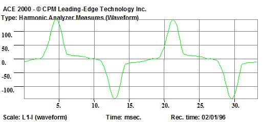
Let’s look now at the readings of the closest panel:
CURRENT
Harmonic Report of L1-I
| Order | Module | Phase Versus |
| THD | 70.69 | |
| DC | 0.53 | |
| 1 | 100.00 | 0.0 (+) |
| 2 | 0.34 | 355.8 (-) |
| 3 | 61.17 | 196.3 (+) |
| 4 | 0.48 | 191.5 (-) |
| 5 | ;33.51 | 23.8 (+) |
| 6 | 0.43 | 4.1 (+) |
| 7 | 10.66 | 202.1 (-) |
| 8 | 0.27 | 215.1 (+) |
| 9 | 3.14 | 333.3 (-) |
VOLTAGE
Harmonic Report of L1-V
| Order | Module | Phase Versus |
| THD | 3.13 | |
| DC | 0.21 | |
| 1 | 100.00 | 0.0 (+) |
| 2 | 0.05 | 37.3 (-) |
| 3 | 1.82 | 43.3 (+) |
| 4 | 0.18 | 278.1 (-) |
| 5 | 2.34 | 211.5 (+) |
| 6 | 0.10 | 269.0 (+) |
| 7 | 0.73 | 332.7 (-) |
| 8 | 0.07 | 76.1 (+) |
| 9 | 0.30 | 60.5 (-) |
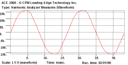
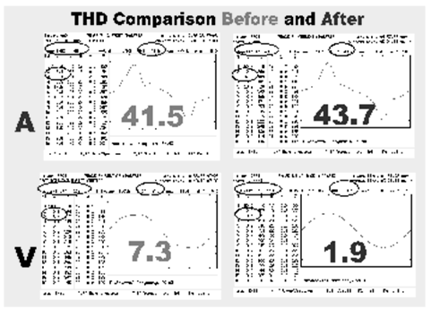
There is a high harmonic current distortion due to the non-linear equipment used in a TV station, but the harmonic voltage is within the IEEE-519 recommended 8% limit.
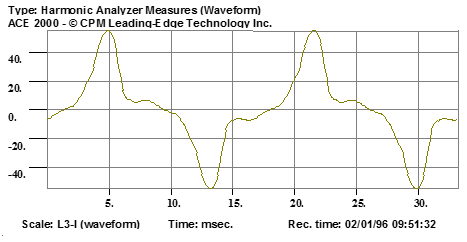
The following example examines the farthest panel with regards to what the long distance and its added impedance will do to the system:
CURRENT
Harmonic Report of L3-I
| Order | Module | Phase Versus |
| THD | 56.48 | |
| DC | 1.15 | |
| 1 | 100.00 | 0.0 (+) |
| 2 | 0.64 | 271.1 (+) |
| 3 | 49.48 | 195.8 (+) |
| 4 | 0.39 | 44.6 (-) |
| 5 | 25.19 | 5.1 (+) |
| 6 | 0.39 | 209.8 (+) |
| 7 | 8.77 | 147.4 (+) |
| 8 | 0.23 | 23.9 (-) |
| 9 | 3.55 | 304.1 (-) |
VOLTAGE
Harmonic Report of L1-V
| Order | Module | Phase Versus |
| THD | 7.62 | |
| DC | 0.33 | |
| 1 | 100.00 | 0.0 (+) |
| 2 | 0.08 | 190.5 (+) |
| 3 | 7.01 | 24.0 (+) |
| 4 | 0.07 | 81.0 (-) |
| 5 | 2.57 | 207.9 (+) |
| 6 | 0.06 | 103.2 (+) |
| 7 | 0.96 | 334.0 (+) |
| 8 | 0.00 | 159.4 (-) |
| 9 | 0.84 | 13.9 (-) |
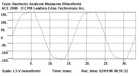
There is now a high harmonic current, but less than the first panel. The harmonic voltage on this panel is near the8% limit of IEEE 519 recommended levels. This will generate a high neutral current and in the same way, because of the Ohms law, a high neutral to ground voltage (common mode).
The filters inside the equipment may leak to the ground making communication troublesome, but this complex subject will be addressed in a separate publication.
The solution was to put a low secondary impedance zero-sequence transformer (Harmonic Mitigating Transformer) close to the studio that was experiencing problems. This transformer is 0° primary to secondary phase shifted, has the capacity of cancelling triplen harmonics on its secondary and has a low impedance (<.95%).
This transformer and the short distance between the applications will reduce voltage distortion below IEEE recommendation as it did for the first transformer with the zero sequence filter.
Cancellation of the 5th and 7th harmonics on this primary bus, which was not cancelled on the secondary of the transformer, will continue due to other transformers phase shifting at 30° (Delta-Wye), causing these harmonics on the primary bus.
Furthermore, grounding is very important to address the problem of noise on the line. If you place the ground wire in series with other transformers, you could notice noise coming back between the studios (ground loops) transferring signals and data through the communication cables.
Triple the size of the isolated ground was run to the water main. The conductors feeding the panels BZR (the secondary of the transformer) were # 3 AWG RW 90. To triple the size, we used 4/0 AWG for the neutrals and isolated grounds. The bare ground for the transformers chassis is # 6 AWG bare. Since we are feeding electronic equipment, we ran an isolated chassis ground # 8 AWG to the panel feeders.
As we transferred the grounding to the new ground system, we also cleaned up most of the noise and hums on the video signals.
CONCLUSION
There is no such thing as a cure for all harmonic problems, although some manufacturers tend to advertise this by making claims on their products. Most of the time, the products consist of MOVs, high frequency filters and sometimes a small transformer (in the best of them), packaged in different shapes and boxes, which are immersed in epoxy (no way to find out what's in it).
Knowledge of all the facts of your application and the proper understanding of current products and solutions, should give you a solution to your electrical problems and above average protection for all the components at your facility.