How Taps Work
Posted: Apr 2,2014
General News
Although power systems have a rated voltage, they often operate at voltages slightly above or below this voltage. This deviation from the rated voltage on the primary side of the transformer is seen on the secondary side of the transformer. Transformers are normally provided with taps to adjust the turns ratio to compensate for this supply variance. This will allow the output voltage to be closer to the rated output voltage when the input voltage is off rated voltage.
What is a Tap?
Each turn on both the high and low voltage coils has the same voltage. This means that the voltage ratio of the high voltage coil compared to the low voltage coil is the same as the ratio of the number of turns in the high voltage coil to the number of turns in the low voltage coil. Taps will add or subtract a number of complete turns to fine tune the turns ratio. Note that partial turn taps are not possible. The industry standard is to supply taps on the primary winding in 2.5% or 5.0% increments of the rated voltage, two above and two or four below rated, to compensate for variation in the supply voltage.
Take a 480 V primary to 120 V secondary single phase transformer. Its primary winding may be wound with 80 turns for 480 V and its secondary winding will have 20 turns for 120 V. For two 2.5% taps above and two 2.5% taps below rated in the primary, each tap will be 2 turns. The primary coil would be wound with a total of 84 turns and have leads to remove 8 turns from the coil in 2 turn steps. This will allow the rated primary voltage of the transformer to be adjusted to any of the following to compensate for variance in the supply voltage and have an output close to 120 V: 504 V, 492 V, 480 V, 468 V and 456 V. This holds true for three phase transformers as well.
Larger transformers are wound with fewer turns. The same 480 V primary to 120 V secondary single phase transformer ratio but a much larger rating may be wound with 24 turns for 480 V and 6 turns for 120 V. Because taps must be made with complete turns, the minimum number of turns between taps would be 1 turn. This means that for this particular transformer, tap increments cannot be any smaller than 4.17% – the industry standard 2.5% taps cannot be achieved. If this same transformer had a primary voltage of 4160 V instead, there would be 208 primary turns and 2.5% taps could be achieved with 5 turns per tap (within the +/- 0.5% tolerance allowed on the turns ratio).
Taps are usually full capacity, meaning that the kVA rating stays the same regardless of the tap position. This means that the rated current on each tap is different – the higher voltage taps have lower rated current and the lower voltage taps have higher rated current. Taps may also be reduced capacity where the current does not increase above rated current for taps at lower than rated voltage. Assume that the 480 V to 120 V example above is rated 30.0 kVA. Rated current at the nominal tap would be 62.5 A. With full capacity taps, the rated current on the 504 V tap would be 59.5 A and the rated current on the 456 V tap would be 65.8 A. If the taps were reduced capacity, the current on the 456 V tap would be 62.5 A, giving a rated kVA on that tap of 28.5 kVA.
Tap Location
The tap turns may be located at one end of the coil or in the middle of the coil. The tap changer is normally a jumper wire bolted to the coil. The tap changer could also be a bolted link on a terminal board. Tap switches could also be supplied, although they are only economical if the taps are changed often.
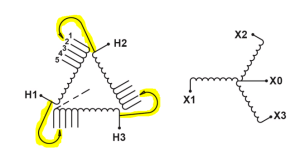
If the turns removed are at the end of the coil, the nameplate diagram will look similar to the high voltage winding in diagram SCD 9, shown in Figure 1 with the tap jumpers highlighted. One end of the tap jumper is fixed to the line terminal and the other end is connected to the appropriate tap on the coil. This is a non-bridging tap arrangement.
Figure 1 - Diagram SCD 9
If the turns are removed from the middle of the coil, the nameplate diagram will look similar to the high voltage winding diagram in SCD 10, shown in Figure 2 with the tap jumpers highlighted.
Figure 2 - Diagram SCD 10
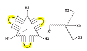
Both ends of the tap jumper are bolted to the coil. A break exists in the coil and the tap jumper joins the two parts of the coil together. This is a bridging tap arrangement. With this type of tap configuration, ensure the tap jumper is connected to a terminal on each side of the break in the winding, i.e. tap 4 to tap 5. Never connect the tap jumper to two terminals on the same side of the break as this will damage the transformer coil.
Changing Taps
Transformers are shipped from the factory in the 100% tap connection. If the tap connection needs to be changed, consult the transformer nameplate for the proper connections. It is important that all coils be set to the same tap position. If the coils are wound with two halves connected in parallel, it is important that both halves have the same connection as well (the nameplate will usually indicate this). Because the transformer must be de-energized to change taps, the choice of tap is based on the long term normal operating voltage of the primary, not compensating for short term fluctuations.
When changing taps, be sure to follow the instructions in the appropriate instruction manual. The first step is to de-energize the transformer and ensure safety grounds are applied to all transformer terminals. When adjusting bolted connections, make sure no hardware goes into a transformer coil – if any does, remove it BEFORE energizing the transformer or the transformer coil could be damaged. Ensure the connecting surfaces are cleaned of insulation, resin and oxidation before making the connection. When sanding or grinding metal, make sure the metal particles do not go into the coils or land on any insulation or terminal board as these could cause a failure in the transformer.
Figure 3 - Damage from improper tap connection
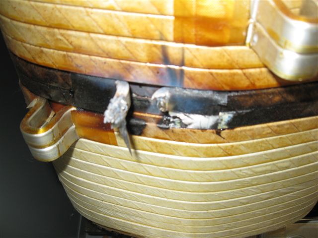
Eye loop taps, found on many 1.2kV class products, require special precautions when changing the taps. They are made by forming a loop of the wire in the winding rather than attaching a pad to the coil. All tap loops other than the 100% tap loops have not been cleaned of insulation or resin at the factory, so it is necessary to clean the loops being used. Remove only the insulation and oxidation, leaving a flat surface for the lug to sit on. Be careful not to remove the metal itself as this is the winding conductor. If the winding is wound with one conductor, one tap jumper is provided per coil and is to be attached to the top of the eye loop. If the winding is wound with two conductors, two tap jumpers are provided. One must be attached to the top and the other must be attached to the bottom – never put both jumpers on the top or bottom only. Figure 3 illustrates what happens when the two jumpers are connected to the top only – note the middle eye loop has completely blown off.
The proper hardware sequence is also important for tap connections, especially for eye loop taps. In newer production, the tap jumper lug is in direct contact with the eye loop. The proper hardware sequence is shown in Figure 4
Figure 4 - Current production eye loop tap connection
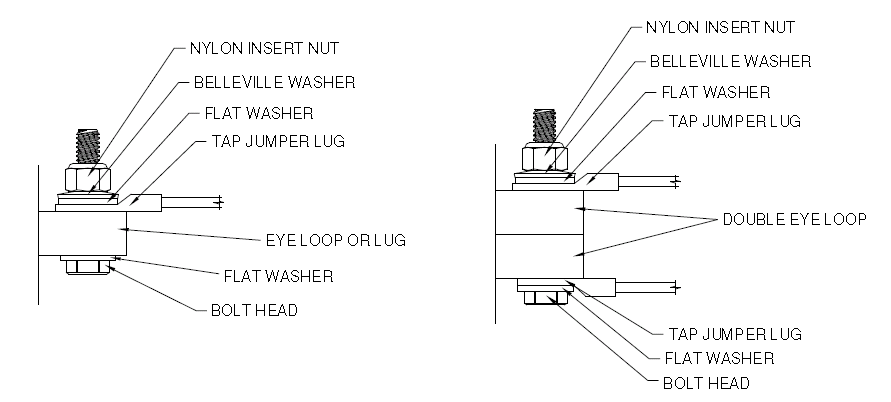
The instruction manuals are being updated to show this. For older production, a tinned brass washer is inserted between the lug and the eye loop – a steel washer here is not acceptable. This is illustrated in Figures 5 and 6.
Figure 5 - Older production single eye loop tap connection
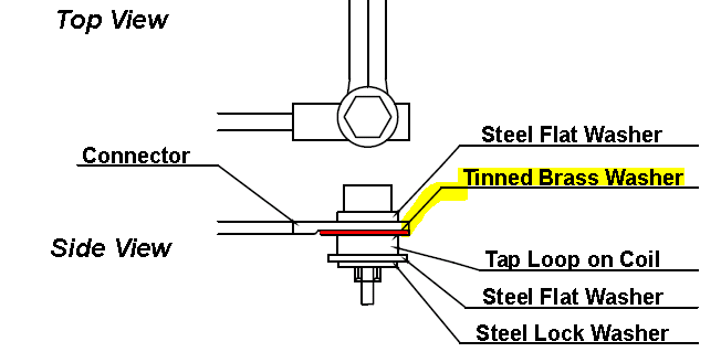
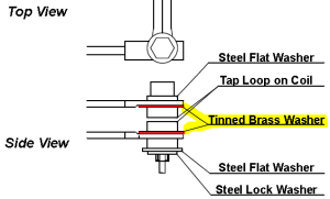
Figure 6 - Older production double eye loop tap connection
For medium voltage transformers above 1.2 kV class, clearance must be provided between the tap jumper cable and other live parts, especially for transformers above 7500 V. The cable insulation is sufficient for contact with live parts of the tap area of the coil it is connected to. The cable insulation may not be adequate for contact with phase or line conductors or ground.
If provided, the tap switch replaces the jumper wire in the previous discussions. All the tap leads would be connected to the switch. The switch would then join the appropriate tap leads together for the selected tap position. Tap switches are available in both bridging and non-bridging configurations. Tap switches are normally designed for operation only when the transformer is de-energized. To change the tap, first de-energize the transformer and apply safety grounds to the transformer terminals. Move the switch from the current position to the desired position. Note that even though a switch is provided, failure to de-energize the transformer when changing taps, even if the switch is called a “no load tap changer”, could result in severe damage to the transformer and tap switch and could also cause personal injury.
The preceding discussion is general in nature regarding the standard tap offering. Other tap options are also available – consult the factory for these. Always consult the transformer nameplate for tap information specific to a particular transformer.