Application Decision Making: Active Harmonic Filters vs. Active Front Ends
About Harmonics
There have been various solutions developed for mitigating harmonic distortion over the past couple of decades. Harmonics became an increasingly important issue as more facilities have begun to use variable frequency drives (VFDs) creating an immense burden on our utility grid. Engineers will attempt to specify the harmonic limits for bus loads, which include switchgear and motor control centers (MCC), in order to help to mitigate this problem.
IEEE-519-2014 provides a guideline for Total Harmonic Distortion (THD) limits that are being increasingly enforced by utility companies around the United States, in an attempt to maintain power quality for their customers. IEEE-519 requires that each facility at the Point of Common Coupling (PCC) meet certain THD levels. These levels are based on several considerations within the facility and the utility that is providing the power. The PCC is clearly defined as the point where the utility power enters the facility, not at each drive input.
These recommendations require facilities to utilize active front ends, 18-pulse drives or use an additional passive or active harmonic filter with a 12-pulse or 6-pulse drive, all of which can significantly increase initial equipment installation costs.
The following article will provide a comparison of drives equipped with an active front end with the use of 6-pulse drives combined with an active harmonic filter. These are both proven methods of decreasing harmonic distortion to below IEEE-519 levels. However before we can compare these two systems we need to take time to give an overview how both of these different solutions work and can aid a facility with harmonic distortion issues.
Active Front End (AFE)
In a regular variable speed drive, the rectifier is implemented with diodes. With an AFE these are replaced with an active, generally IGBT based, controlled rectifier. This active rectifier creates canceling harmonics that effectively eliminate those created in standard VFDs. The figure below shows the components of an AFE, including the active rectifier, DC energy storage, and inverter. Because of its series installation the active rectifier needs to be able to transmit the full power of the load. In addition to performing harmonic correction, the active front end rectifier has the ability to feed electrical energy back to the utility during braking. AFE drives usually have very low current distortion (often down to 5% THD) and high power factor. The ability to feed back braking energy is very useful in some applications; while in others, AFEs are only installed for their effectiveness at reducing harmonic distortion.
 In order to make the AFE as light and compact as possible, the switching frequency of the active rectifier must be relatively low. This lower switching frequency creates a higher switching ripple, which can introduce harmonics above the 50th order. These higher-order harmonics can negatively affect the performance of some equipment. In order to mitigate these concerns the switching frequency must be increased. However, manufacturers do not typically take this approach because the active rectifier becomes physically larger and more expensive. The rectifier also creates a voltage boost on the DC bus voltage when compared to a conventional 6-pulse drive. This higher DC bus voltage creates a higher ripple on the motor side, which may require a dV/dT filter be placed to protect the motor/load.
Active Harmonic Filters (AHFs)
Active harmonic filters use intelligent electronics and IGBTs to inject corrective current into the power system to correct for the harmonics generated by non-linear loads. Systems are installed in parallel to the utility line and sensors are used to monitor the line and determine the amount of corrective current that must be injected to ensure the utility provides a sinusoidal waveform.
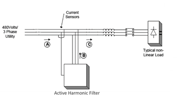 Active harmonic filters can be used to compensate for both harmonic distortion and power factor, and one unit can be used to compensate for multiple non-linear loads. It is able to operate at its maximum current rating and not be overloaded, even if new loads are installed. Multiple active harmonic filters can be installed in parallel to supply corrective current for larger applications. They are able to function properly if voltage imbalances exist. Active harmonic filters can be a more costly solution for a single drive application, but since one filter can be used to correct for multiple loads, they clearly become a more cost effective solution as the number of non-linear loads increases.
Comprehensive Comparison
Advantages of Active Front Ends
- Some cost savings can be realized in comparison to active harmonic filters if there is a single, large drive present in the application
- Provides increased input protection for a VFD and its semiconductors from line transients
- Systems are insensitive to network imbalance present in the line
- Will be IEEE-519 compliant under most operating conditions
- Has a extremely high power factor (up to 0.99)
- Able to feed energy back to the grid during braking effectively reducing utility costs
Advantages of Active Harmonic Filters
- While an AFE meets the harmonic limits specified in IEEE-519, an active harmonic filter, if sized correctly, guarantees that the standard is met, making THD less than 5% regardless if the VFDs are not operating near maximum load
- One Active Harmonic Filter can correct for multiple 6-pulse drive systems, while if using one AFE, a rectifier is required for each drive, which can become costly if the application has multiple VFDs
- Active Harmonic Filters introduce significantly less switching ripple than an AFE because of its use of a higher switching frequency and smaller size in comparison to the load
- If maintenance is required on an AFE drive then downtime is needed. Since an active harmonic filter is installed in parallel it can be maintained while the drive(s) are running
- An Active Harmonic Filter, if appropriately sized, can correct power factor and balance the line while simultaneously correcting the facilities/application harmonic distortion.
- Parallel installation of active harmonic filters provides for easy installation with no major system rework, while the installation of a AFE requires complete replacement of each existing drive
- Active Harmonic Filters can be integrated with MCC’s switch gear, which dramatically save space and costs when compared to an AFE, whose footprints’ may be a concern, especially for retrofit projects
- Active Harmonic Filters have less losses and increased efficiency, which decreases electricity and cooling costs when compared to series type AFE arrangements
- Maintenance, repair, and replacement of 6-pulse drives combined with an active harmonic filter are significantly faster and less complicated than that of Active Front Ends.
Conclusions
Both systems are effective at mitigating harmonic distortion and meeting IEEE-519, and it often depends on each individual facility to determine which application to use. Certain situations where a single large VFD is present an Active Front End may be the more cost effective option, however active harmonic filters can be more cost effective if there are multiple VFDs (non-linear loads) in the facility. The Active Harmonic Filter is the only solution to guarantee that IEEE-519 recommendations are met, even when voltage unbalance exists or if a load is not expected to run at its maximum (which are both common).
References
- D.J. Carnovale, “Applying Harmonic Solutions to Commercial Systems.” Globalcon, 2003, Boston, MA.
- IEEE Standard 519-1992-IEEE Recommended Practices and Requirements for Harmonic Control in Electrical Power Systems
- Kelly, Rob. “Active Front End Variable Frequency Drives.” Pumps & Systems Magazine. Emerson Control Techniques, 2010. Web. 11 June 2014.
- Singh, B.; Al-Haddad, K. and Chandra, A. (1999) A review of active filters for power quality improvement”, IEEE Trans. Industrial Electronics, vol. 46, no. 5, pp. 960-971.
- "CDA Magazine – Reducing Harmonics with Filter or Active Front-End Drives?”18 Sept. 2012. Web. 11 June 2014.
- Nick Guskov, “Straight Talk about PWM AC Drive Harmonic Problems and Solutions.” Rockwell Automation, Mequon, WI.
- Persson, Jonas. “Comparing Harmonics Mitigation Techniques.” (2014): n. pag. Web. 10 June 014.